ESC Calibration
BLDC(BrushLess DC) 모터를 제어하기 위해서는 ESC(Electronic Speed Controller)를 사용하는데, ESC에 PWM 신호를 입력하여 모터의 회전 속도를 조절하게 된다. 이에 앞서, ESC Calibration이라는 작업을 필수로 해주어야 하는데, 간단히 말하면 조종기의 최대(MAX) 및 최소(MIN) PWM 신호값을 ESC에 mapping 시켜주는 과정이다.
최종적으로는 STM32F103으로 SimonK 30A ESC라는 제품을 Calibration 및 test하는게 목적이지만, ESC Calibration을 처음 진행해보기에 저는 먼저 코드자료가 많은 Arduino를 이용해 구동을 시켜보고 그 해당 소스를 STM32F103 환경에 맞게 바꾸는 과정으로 최종적인 목표를 달성할 것이다.
1. Arduino ESC Calibration
운이 좋게도 잘 정리해놓은 아두이노 코드를 찾았다. 연결은 다음과 같이 진행하면 되고, 쿼드콥터를 기준으로 구성된 소스기 때문에 모터 4개에 대한 Calibration을 진행한다.
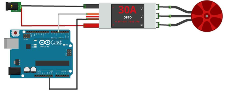
PIN Connection
- ESC1 to Arduino's digital pin #4
- ESC2 to Arduino's digital pin #5
- ESC3 to Arduino's digital pin #6
- ESC4 to Arduino's digital pin #7
Code
|
1
2
3
4
5
6
7
8
9
10
11
12
13
14
15
16
17
18
19
20
21
22
23
24
25
26
27
28
29
30
31
32
33
34
35
36
37
38
39
40
41
42
43
44
45
46
47
48
49
50
51
52
53
54
55
56
57
58
59
60
61
62
63
64
65
66
67
68
69
70
71
72
73
74
75
76
77
78
79
80
81
82
83
84
85
86
87
88
89
90
91
92
93
94
95
96
97
98
99
|
// ---------------------------------------------------------------------------
#include <Servo.h>
// ---------------------------------------------------------------------------
// Customize here pulse lengths as needed
#define MIN_PULSE_LENGTH 1000 // Minimum pulse length in µs
#define MAX_PULSE_LENGTH 2000 // Maximum pulse length in µs
// ---------------------------------------------------------------------------
Servo motA, motB, motC, motD;
char data;
// ---------------------------------------------------------------------------
/**
* Initialisation routine
*/
void setup() {
Serial.begin(9600);
motA.attach(4, MIN_PULSE_LENGTH, MAX_PULSE_LENGTH);
motB.attach(5, MIN_PULSE_LENGTH, MAX_PULSE_LENGTH);
motC.attach(6, MIN_PULSE_LENGTH, MAX_PULSE_LENGTH);
motD.attach(7, MIN_PULSE_LENGTH, MAX_PULSE_LENGTH);
displayInstructions();
}
/**
* Main function
*/
void loop() {
if (Serial.available()) {
data = Serial.read();
switch (data) {
// 0
case 48 : Serial.println("Sending minimum throttle");
motA.writeMicroseconds(MIN_PULSE_LENGTH);
motB.writeMicroseconds(MIN_PULSE_LENGTH);
motC.writeMicroseconds(MIN_PULSE_LENGTH);
motD.writeMicroseconds(MIN_PULSE_LENGTH);
break;
// 1
case 49 : Serial.println("Sending maximum throttle");
motA.writeMicroseconds(MAX_PULSE_LENGTH);
motB.writeMicroseconds(MAX_PULSE_LENGTH);
motC.writeMicroseconds(MAX_PULSE_LENGTH);
motD.writeMicroseconds(MAX_PULSE_LENGTH);
break;
// 2
case 50 : Serial.print("Running test in 3");
delay(1000);
Serial.print(" 2");
delay(1000);
Serial.println(" 1...");
delay(1000);
test();
break;
}
}
}
/**
* Test function: send min throttle to max throttle to each ESC.
*/
void test()
{
for (int i = MIN_PULSE_LENGTH; i <= MAX_PULSE_LENGTH; i += 5) {
Serial.print("Pulse length = ");
Serial.println(i);
motA.writeMicroseconds(i);
motB.writeMicroseconds(i);
motC.writeMicroseconds(i);
motD.writeMicroseconds(i);
delay(200);
}
Serial.println("STOP");
motA.writeMicroseconds(MIN_PULSE_LENGTH);
motB.writeMicroseconds(MIN_PULSE_LENGTH);
motC.writeMicroseconds(MIN_PULSE_LENGTH);
motD.writeMicroseconds(MIN_PULSE_LENGTH);
}
/**
* Displays instructions to user
*/
void displayInstructions()
{
Serial.println("READY - PLEASE SEND INSTRUCTIONS AS FOLLOWING :");
Serial.println("\t0 : Send min throttle");
Serial.println("\t1 : Send max throttle");
Serial.println("\t2 : Run test function\n");
}
|
아두이노 코드 출처 : https://github.com/lobodol/ESC-calibration
Usage
After having uploaded sketch on your Arduino and having ESCs not powered up yet :
- Plug your Arduino to your computer with USB cable, open terminal, then type 1️⃣. This will send max throttle to each ESC in order to make them enter programming mode.
- Power up your ESCs. You must hear "beep1 beep2 beep3" tones meaning the power supply is OK.
- After 2sec, "beep beep" tone emits, meaning the throttle highest point has been correctly confirmed.
- Then, type 0️⃣ to send 0 throttle. This will set the lowest throttle level for each ESC.
- Several "beep" tones emits, wich means the quantity of the lithium battery cells (3 beeps for a 3 cells LiPo).
- A long beep tone emits meaning the throttle lowest point has been correctly confirmed. Your ESC's are now well calibrated and ready for test.
- Type 2️⃣ to launch test function. This will send 0 to max throttle to ESCs : you must see your motors starting to run with increasing speed, then stop when maximum speed is reached.
2. STM32F103 ESC Calibration (IAR Embedded Workbench)
위 아두이노 소스를 IAR Embedded Workbench를 통한 STM32F103 제어에 맞게 소스를 변경할 것이다.
시리얼 통신 프로그램으로는 Realterm이라는 프로그램을 사용했다. (해당 블로그의 유틸리티 카테고리에 올려져있음)
전체소스코드는 https://github.com/jeonds1127/stm32f103_quadcopter.git
PIN Connection
- ESC1 to STM32F103RB's digital pin PB9(TIM4->CCR4)
- ESC2 to STM32F103RB's digital pin PB0(TIM3->CCR3)
- ESC3 to STM32F103RB's digital pin PB1(TIM3->CCR4)
- ESC4 to STM32F103RB's digital pin PB8(TIM4->CCR3)
Code
> main.c
|
1
2
3
4
5
6
7
8
9
10
11
12
13
14
15
16
17
18
19
20
21
22
23
24
25
26
27
28
29
30
31
32
33
34
35
36
37
38
39
40
41
42
43
44
45
46
47
48
49
50
51
52
53
54
55
56
57
58
59
60
61
62
63
64
65
66
67
68
69
70
71
72
73
74
75
76
77
78
79
80
81
82
83
84
85
86
87
88
89
90
91
92
93
94
95
96
97
98
99
100
101
102
|
#include "hw_config.h"
#include <stdio.h>
// Customize here pulse lengths as needed
#define MIN_PULSE_LENGTH 1000 // Minimum pulse length in ¥ìs
#define MAX_PULSE_LENGTH 2000 // Maximum pulse length in ¥ìs
#define PWM_MOTOR1 TIM4->CCR4 // PB9
#define PWM_MOTOR2 TIM3->CCR3 // PB0
#define PWM_MOTOR3 TIM3->CCR4 // PB1
#define PWM_MOTOR4 TIM4->CCR3 // PB8
/* Global variables */
RCC_ClocksTypeDef rcc_clocks;
void displayInstructions()
{
printf("READY - PLEASE SEND INSTRUCTIONS AS FOLLOWING :\n");
printf("\t0 : Send min throttle\n");
printf("\t1 : Send max throttle\n");
printf("\t2 : Run test function\n\n");
}
void test()
{
for (int i = MIN_PULSE_LENGTH; i <= MAX_PULSE_LENGTH; i += 5) {
printf("Pulse length = ");
printf("%d\n",i);
PWM_MOTOR1 = i;
PWM_MOTOR2 = i;
PWM_MOTOR3 = i;
PWM_MOTOR4 = i;
delay_ms(200);
}
printf("STOP");
PWM_MOTOR1 = MIN_PULSE_LENGTH;
PWM_MOTOR2 = MIN_PULSE_LENGTH;
PWM_MOTOR3 = MIN_PULSE_LENGTH;
PWM_MOTOR4 = MIN_PULSE_LENGTH;
}
int main(void)
{
char ch;
/* System Clocks Configuration */
RCC_Configuration();
RCC_GetClocksFreq(&rcc_clocks);
/* Setup SysTick Timer for 10usec interrupts */
if (SysTick_Config(rcc_clocks.SYSCLK_Frequency / 100000))while (1);
/* Configure the GPIO ports */
GPIO_Configuration();
/* Reset */
USART1_Init(); printf("USART : OK\n");
Motor_Init();
delay_ms(100);
displayInstructions();
while(1)
{
ch = USART_GetCharacter(USART1);
switch ((char)ch) {
// 0
case '0' :
printf("Sending minimum throttle\n");
PWM_MOTOR1 = MIN_PULSE_LENGTH;
PWM_MOTOR2 = MIN_PULSE_LENGTH;
PWM_MOTOR3 = MIN_PULSE_LENGTH;
PWM_MOTOR4 = MIN_PULSE_LENGTH;
break;
// 1
case '1' :
printf("Sending maximum throttle\n");
PWM_MOTOR1 = MAX_PULSE_LENGTH;
PWM_MOTOR2 = MAX_PULSE_LENGTH;
PWM_MOTOR3 = MAX_PULSE_LENGTH;
PWM_MOTOR4 = MAX_PULSE_LENGTH;
break;
// 2
case '2' :
printf("Running test in 3\n");
delay_ms(1000);
printf(" 2");
delay_ms(1000);
printf(" 1...");
delay_ms(1000);
test();
break;
}
ch = 0;
}
}
|
> config.c
|
1
2
3
4
5
6
7
8
9
10
11
12
13
14
15
16
17
18
19
20
21
22
23
24
25
26
27
28
29
30
31
32
33
34
35
36
37
38
39
40
41
42
43
44
45
46
47
48
49
50
51
52
53
54
55
56
57
58
59
60
61
62
63
64
65
66
67
68
69
70
71
72
73
74
75
76
77
78
79
80
81
82
83
84
85
86
87
88
89
90
91
92
93
94
95
96
97
98
99
100
101
102
103
104
105
106
107
108
109
110
111
112
113
114
115
116
117
118
119
120
121
122
123
124
125
126
127
128
129
130
131
132
133
134
135
136
137
138
139
140
141
142
143
144
145
146
147
148
149
150
151
152
153
154
155
156
157
158
159
160
161
162
163
164
165
166
167
168
169
170
171
172
173
174
175
176
177
178
179
180
181
182
183
184
185
186
187
188
189
190
191
|
#include "hw_config.h"
#include "stm32f10x_tim.h"
/* global variables */
static volatile uint32_t TimingDelay;
/* functions */
void delay_ms(__IO uint32_t nTime)
{
TimingDelay = nTime * 100; // 10 us * nTime * 100 -> 1ms * nTime
while(TimingDelay != 0);
}
void delay_10us(__IO uint32_t nTime)
{
TimingDelay = nTime;
while(TimingDelay != 0);
}
void TimingDelay_Decrement(void)
{
if (TimingDelay != 0x00)
{
TimingDelay--;
}
}
/* defines */
#ifdef __GNUC__
#define PUTCHAR_PROTOTYPE int __io_putchar(int ch)
#else
#define PUTCHAR_PROTOTYPE int fputc(int ch, FILE *f)
#endif /* __GNUC__ */
void USART1_Init(void)
{
USART_InitTypeDef USART_InitStructure;
/* USARTx configuration ------------------------------------------------------*/
/* USARTx configured as follow:
- BaudRate = 115200 baud
- Word Length = 8 Bits
- One Stop Bit
- No parity
- Hardware flow control disabled (RTS and CTS signals)
- Receive and transmit enabled
*/
USART_InitStructure.USART_BaudRate = 115200;
USART_InitStructure.USART_WordLength = USART_WordLength_8b;
USART_InitStructure.USART_StopBits = USART_StopBits_1;
USART_InitStructure.USART_Parity = USART_Parity_No ;
USART_InitStructure.USART_HardwareFlowControl
= USART_HardwareFlowControl_None;
USART_InitStructure.USART_Mode = USART_Mode_Rx | USART_Mode_Tx;
/* Configure the USARTx */
USART_Init(USART1, &USART_InitStructure);
USART_ITConfig(USART1, USART_IT_RXNE, ENABLE);
/* Enable the USART1 */
USART_Cmd(USART1, ENABLE);
}
void Motor_Init(void)
{
TIM_TimeBaseInitTypeDef TIM_TimeBaseStructure;
TIM_OCInitTypeDef TIM_OCInitStructure;
GPIO_InitTypeDef GPIO_InitStructure;
GPIO_InitStructure.GPIO_Pin = GPIO_Pin_0 | GPIO_Pin_1 | GPIO_Pin_8 | GPIO_Pin_9;
GPIO_InitStructure.GPIO_Mode = GPIO_Mode_AF_PP;
GPIO_InitStructure.GPIO_Speed = GPIO_Speed_50MHz;
GPIO_Init(GPIOB, &GPIO_InitStructure);
/* TIM4 */
RCC_APB1PeriphClockCmd(RCC_APB1Periph_TIM4, ENABLE);
/* Time base configuration */
TIM_TimeBaseStructure.TIM_Period = 20000 - 1;
TIM_TimeBaseStructure.TIM_Prescaler = 72 - 1;
TIM_TimeBaseStructure.TIM_ClockDivision = 0;
TIM_TimeBaseStructure.TIM_CounterMode = TIM_CounterMode_Up;
TIM_TimeBaseInit(TIM4, &TIM_TimeBaseStructure);
TIM_OCInitStructure.TIM_OCMode = TIM_OCMode_PWM1;
TIM_OCInitStructure.TIM_OutputState = TIM_OutputState_Enable;
TIM_OCInitStructure.TIM_OCPolarity = TIM_OCPolarity_High;
TIM_OCInitStructure.TIM_Pulse = 0;
TIM_OC3Init(TIM4, &TIM_OCInitStructure);
TIM_OC4Init(TIM4, &TIM_OCInitStructure);
TIM_OC3PreloadConfig(TIM4, TIM_OCPreload_Enable);
TIM_OC4PreloadConfig(TIM4, TIM_OCPreload_Enable);
/* TIM4 enable counter */
TIM_Cmd(TIM4, ENABLE);
/* TIM3 */
RCC_APB1PeriphClockCmd(RCC_APB1Periph_TIM3, ENABLE);
/* Time base configuration */
TIM_TimeBaseStructure.TIM_Period = 20000 - 1;
TIM_TimeBaseStructure.TIM_Prescaler = 72 - 1;
TIM_TimeBaseStructure.TIM_ClockDivision = 0;
TIM_TimeBaseStructure.TIM_CounterMode = TIM_CounterMode_Up;
TIM_TimeBaseInit(TIM3, &TIM_TimeBaseStructure);
TIM_OCInitStructure.TIM_OCMode = TIM_OCMode_PWM1;
TIM_OCInitStructure.TIM_OutputState = TIM_OutputState_Enable;
TIM_OCInitStructure.TIM_OCPolarity = TIM_OCPolarity_High;
TIM_OCInitStructure.TIM_Pulse = 0;
TIM_OC3Init(TIM3, &TIM_OCInitStructure);
TIM_OC4Init(TIM3, &TIM_OCInitStructure);
TIM_OC3PreloadConfig(TIM3, TIM_OCPreload_Enable);
TIM_OC4PreloadConfig(TIM3, TIM_OCPreload_Enable);
/* TIM3 enable counter */
TIM_Cmd(TIM3, ENABLE);
TIM_ITConfig(TIM3, TIM_IT_Update, ENABLE);
}
void RCC_Configuration(void)
{
SystemInit(); // 72MHz Enable
/* Enable GPIO clock */
RCC_APB2PeriphClockCmd(RCC_APB2Periph_GPIOA|RCC_APB2Periph_GPIOB|RCC_APB2Periph_GPIOD, ENABLE);
RCC_APB2PeriphClockCmd(RCC_APB2Periph_USART1, ENABLE);
}
void GPIO_Configuration(void)
{
GPIO_InitTypeDef GPIO_InitStructure;
/* Configure USARTx_Tx as alternate function push-pull */
GPIO_InitStructure.GPIO_Pin = GPIO_USART_Tx_Pin;
GPIO_InitStructure.GPIO_Speed = GPIO_Speed_50MHz;
GPIO_InitStructure.GPIO_Mode = GPIO_Mode_AF_PP;
GPIO_Init(GPIO_USART, &GPIO_InitStructure);
/* Configure USARTx_Rx as input floating */
GPIO_InitStructure.GPIO_Pin = GPIO_USART_Rx_Pin;
GPIO_InitStructure.GPIO_Mode = GPIO_Mode_IN_FLOATING;
GPIO_Init(GPIO_USART, &GPIO_InitStructure);
}
PUTCHAR_PROTOTYPE
{
/* Write a character to the USART */
if( ch == '\n') {
USART_SendData(USART1, '\r');
while(USART_GetFlagStatus(USART1, USART_FLAG_TXE) == RESET);
USART_SendData(USART1, '\n');
}else {
USART_SendData(USART1, (u8) ch);
}
/* Loop until the end of transmission */
while(USART_GetFlagStatus(USART1, USART_FLAG_TXE) == RESET);
return ch;
}
uint8_t USART_GetCharacter(USART_TypeDef * usart_p)
{
uint8_t data;
/* Loop until the end of transmission */
while(USART_GetFlagStatus(usart_p, USART_FLAG_RXNE) == RESET);
/* Write a character to the USART */
data = USART_ReceiveData(usart_p);
USART_SendData(usart_p, data);
while(USART_GetFlagStatus(usart_p, USART_FLAG_TXE) == RESET);
if( data == '\r' ) return (int)('\n');
else return(data);
}
|
Usage
아두이노와 동일.
PWM period는 20ms로 설정되있으며 그 안에서 duty를 1~2ms로 줌으로써 제어를 하고 있다. 쿼드콥터나 기타 모터의 빠른 반응속도를 요구하는 시스템에서는 PWM period가 20ms면 매우 느리기때문에 값의 수정이 필요하다.
'Embedded System > STM32F103' 카테고리의 다른 글
| [STM32F103] Quadcopter Project (0) | 2019.11.12 |
|---|